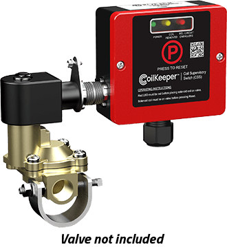
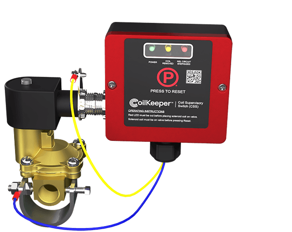
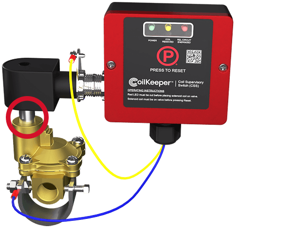
CoilKeeper™ Solenoid Supervisory Switch
Meets New NFPA 13 Code!
Potter's CoilKeeper Supervisory Switch is designed to supervise the position of a coil on a solenoid for a preaction/deluge system as required by NFPA 13 (8.3.1.2.1). The unit monitors the coil electronically and determines if the coil is installed on the valve stem. If a technician removes the actuator from the stem, the CoilKeeper will activate a normally open set of dry contacts that can be wired to a supervisory circuit of the releasing control panel.
Local LEDs show when the coil is in the following states:
- Normal state on the valve body
- The actuator is removed from the valve body in a maintenance state
- The releasing circuit is energized
- The coil is open or shorted
A LED indicates that the releasing circuit is energized allowing the technician to see the state of the circuit, preventing accidental release by re-installing an energized coil.

Operation
Actuator Properly Installed
When the actuator is properly installed, pressing reset on the CoilKeeper will clear any previous supervisory signals and the CoilKeeper will indicate a normal state.
Actuator Improperly Installed
If the actuator is improperly installed, continuity or inductance tests will fail, resulting in a supervisory state. Ensure actuator is properly installed on the solenoid body following the manufacturer's instructions to clear supervisory state.
Actuator Missing
The CoilKeeper will also go into a supervisory state if the actuator is completely removed. The CoilKeeper latches and requires the actuator to be properly installed and CoilKeeper reset to clear the supervisory signal.
Remote Installation
In addition to direct installation onto the solenoid, the CoilKeeper can be remotely mounted wherever convenient. Wires attach to the included sense bracket and clamp to complete a circuit through the coil.

Required by Code

As of January 1, 2021, NFPA 13 requires indication of a disconnected actuator with a trouble signal at the releasing panel:
8.3.1.2.1 Actuator Supervision.
Effective January 1, 2021, removal of an electric actuator from the preaction or deluge valve that it controls shall result in an audible and visual indication of system impairment at the system releasing control panel.
NFPA 13, "Standard for the Installation of Sprinkler Systems," 2019 edition
© 2018 National Fire Protection Association
Potter's CoilKeeper meets the code and provides supervision for most releasing solenoids. For a full compatibility list, click here.
CoilKeeper™ Features

Visual Indication of Coil Status
Local LEDs at the CoilKeeper show when the coil is in a normal state on the valve body, when the coil is removed from the valve body in a maintenance state, when the releasing circuit is energized, and if the coil is open or shorted. The releasing circuit energized LED allows the technician to locally see the state of the circuit, preventing accidental release by re-installing an energized coil.
Detects Open & Shorted Coils
The CoilKeeper will indicate if the coil needs to be replaced due to opens or shorts.
Difficult to Defeat
The CoilKeeper uses multiple electrical measurements to ensure the coil is intact, making it the most difficult to defeat actuator supervisory solution.
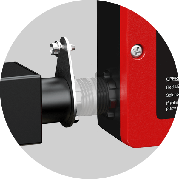
Direct or Remote Installation
The CoilKeeper can be installed directly onto the valve with the supplied 1/2" pipe nipple. If the valve configuration does not allow for direct mounting, the CoilKeeper can be remotely connected wherever wiring is convenient.

Powered by Fire Panel 24VDC
The CoilKeeper is powered directly from the releasing panel and does not require a separate supply. It can connect to any fire panel or releasing panel.
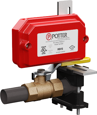
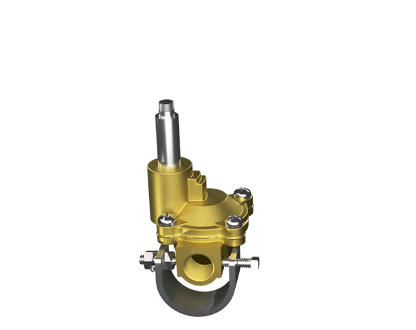
A Mechanical Solution
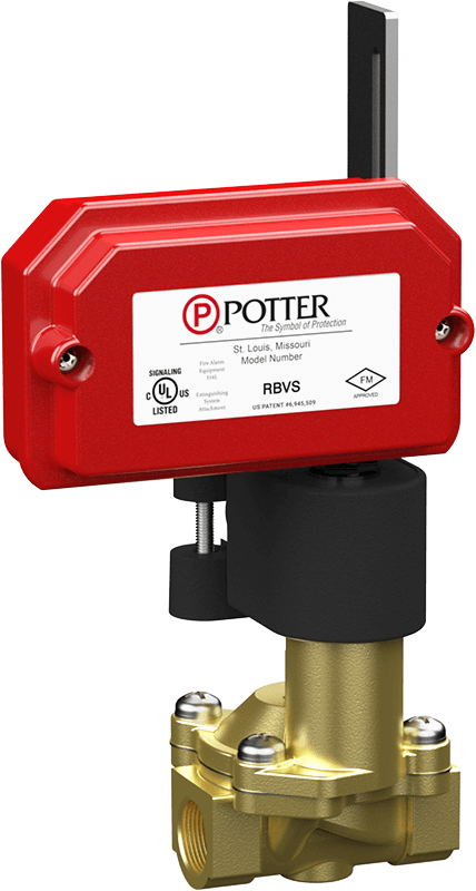
In addition to the CoilKeeper, Potter's updated RBVS provides a mechanical solution to meet NFPA 13 code. The RBVS includes a small "L" bracket and "V" clamp to allow the RBVS to mount directly to the nipple on the coil of a solenoid valve. The plunger of the RBVS is actuated by the stud protruding through the center of the coil. If a technician removes the coil from the solenoid for testing, the RBVS will activate.
RBVS
- Monitors the position of a coil on a solenoid
- Indicates trouble signal to releasing panel