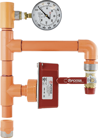
 The RD13 Riser (with NPT connectors) is constructed from Listed CPVC products suitable for fire sprinkler services subject to the limitations and installation requirements of Flameguard® CPVC pipe and Spears® CPVC fittings. The RD13 Riser incorporates a VSR-SG flow switch, gauge, and drain/test valve. The VSR-SG flow switch is equipped with union connection to facilitate the installation and removal of the switch in confined spaces.
Unique Features
- Includes flowswitch with union coupling for installations with limited space
- Fits between studs on standard 2 x 4 wall construction
- 0-90 Second retard to prevent unwanted alarms
- The female threaded inlet is shipped loose for easier installation
- Easy to read clearly marked terminal strip makes wiring easier
- Visual and audible indications of switch activation
Codes and Approvals
- VSR-SG flowswitch is UL, cUL and CSFM Listed
- Riser and flowswitch comply with requirements for NFPA 13, 13D 13R and 72
Engineering Specifications
Residential Riser / Flowswitch Assembly: Furnish and install riser assembly where indicated on the plans and drawings and as required by applicable local and national codes and standards. The riser shall be constructed from Listed CPVC material suitable for fire sprinkler service and sized to fit within standard 2x4 wall construction. The riser shall consist of a female NPT connection at the riser inlet sized the same as the riser for connection to the water supply, a Tee with a 1” factory glued-in CPVC spigot to allow for installation of the flowswitch, 1” test / drain line with 3.5” 300 psi pressure gauge on the riser above the test / drain line. The riser shall include a Listed vane type waterflow switch. All wetted parts of the waterflow switch shall be non-metallic. The flowswitch shall consist of a factory installed paddle designed specifically for the size and make of the CPVC Tee it will be installed in on the riser, a 1” CPVC union for connection to the spigot on the riser, 0-90 second field replaceable adjustable time delay switch mechanism to prevent false alarms from water surges and two conduit entrances. Waterflow switch enclosure shall be NEMA 4 rated and shall be held captive by tamper resistant screws. It shall be possible to install an optional cover tamper switch to detect removal of the enclosure. The flowswitch shall be listed for pressures up to 175 psi, maximum water surges of 18 fps and alarm activation by 10gpm. Activation shall be accomplished by the continuous flow of water against a non-corrosive vane or paddle attached to a non-corrosive stem operating a field replaceable instantly recycling adjustable retard with a visual indication of activation. Expiration of the retard time shall result in the simultaneous operation of two sets of single pole double throw (SPDT) switch contacts rated at 10A, 125VAC and 2A, 30VDC. Each switch contact shall have a separate wiring chamber and separate conduit entrance to comply with the NEC requirements for separation of power limited and non power limited conductors without the need for special wire or wire methods.
Additional Information for Engineers:
- Factory assembled and pressure tested
- Manufactured from Listed components
- Simple proven design
- Physical barriers on switches allow easier compliance with NEC requirements for separation of voltages
Installation Tips
- There is no check valve on the riser because most municipalities require a BackFlow Preventor so an additional check valve would create unnecessary friction loss
- Read and Follow installation instructions for CPVC
Tech Tips
- Wiring the VSR to operate a bell is the same as wiring a light switch to turn on a light. Run Neutral wire from the source directly to the neutral on ther bell. Run the hot wire to the COM terminal. Run the switched wire from the N.O. terminal to the black wire on the bell.
- The retard can be field replaced without draining the system or removing the flowswitch
Additional Information
- Saves contractors time and money compared to building their own risers from scratch!
Click here to view more info about the RD13
For additional questions, contact customer service: sales@pottersignal.com, or tech support: tech@pottersignal.com
